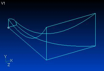
1. Import CAD geometry
2. Define surfaces from imported lines and curves
|
|
PAFEC VibroAcoustics - Import of CAD data to create horn model |
|
|
Third party pre-processing software can be used to import CAD
data and generate a mesh, which can be
straightforwardly converted to PAFEC data file format.
|
|
|
1. Import CAD geometry
|
|
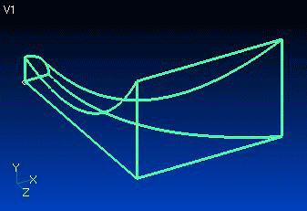
2. Define surfaces from imported lines and curves
|
|
|
|
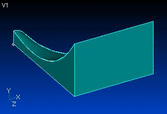
3. Define volume from surfaces |
|
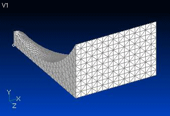
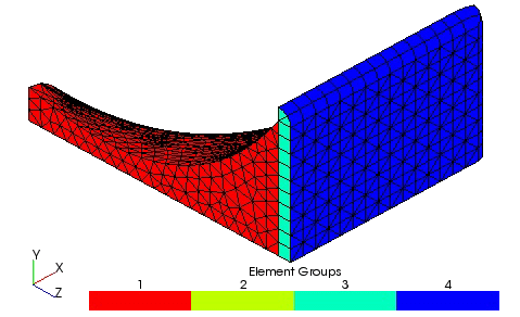
4. Assign appropriate mesh size |
|
|
|
Please note, it may be necessary to repair CAD data if
edges do not meet at verticies
|
|
||
|
|
5. Convert to PAFEC format
|
|
The wizard Horn.exe converts the mesh to PAFEC data file format and adds additional modules to describe:
|
|
|
|
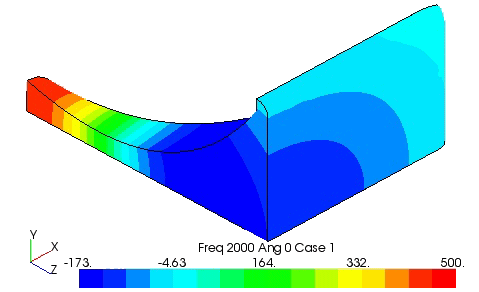
6. Run PAFEC analysis and post-process results
|
|
Various result types and formats are available, including:
|
|
|
|
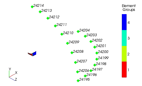
7. Position of microphone nodes
|
|
The position of the microphone: in this instance two quarter
circles at 90o to each other, at 5o
steps, 1m from the mouth of the horn.
|
|
|
|
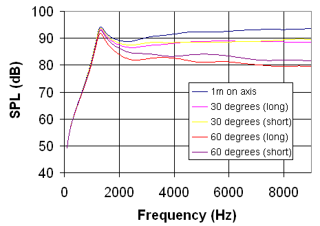
8. Graph of SPL (dB) v Frequency (Hz) for selected microphone nodes
|
|
|
|
| Back |
|